EV charging equipment in the event of certain faults relies on automatic supply disconnection to protect the user and other members of the public. To reduce the chances of receiving a fatal shock, RCDs must operate before the residual current reaches a dangerous level and within the defined disconnection time. This protection feature will be ineffective where inappropriate RCDs are specified or installed.
RCD “Blinding”
Electrical engineers selecting RCDs for EV Charge Point applications should not think purely in terms of smooth d.c. residual current. The standards[1] relating to EV installations actually refer to “d.c. component”; i.e. any current with a permanent +ve or –ve bias that does not pass through zero on every ½ cycle. The level and characteristics of these currents in normal operation and under certain fault conditions can result in reduced sensitivity or “Blinding” due to magnetic saturation of the RCD sensing circuit, and therefore reduced protection for the public. The design characteristics of EV chargers vary and consequently EV manufactures specify the type of RCD that can be used safely when charging from mode 1, 2 or 3 installations.
The key points related to “SAFE” EV charge point RCD selection:
- On-Board EV charger design impacts on the RCD selection – check with EV manufacture
- Some chargers produce wave forms that cause nuisance tripping or worse RCD blinding
- Type A RCDs operate in the presence of 50Hz pulsed wave form with <6mA smooth dc content
- Type A RCDs are designed to operate on a standard 50Hz[2] sine wave supply defined in the standard
Type A RCD operating principles- see fig 1
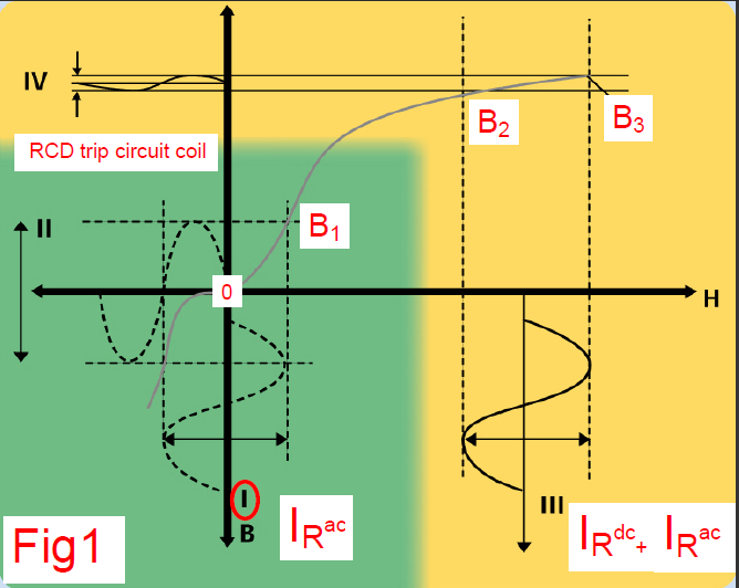 Hysteresis curve[3] 0 to B3 represents the +ve half of RDC toroid magnetic characteristic, the green area represents optimum operational area, yellow represents the area of increasing magnetic saturation. A 50Hz residual current IRac, (I) equal to the tripping value sensitivity, produces a magnetic field 0 to B1 for the +ve ½ cycle. The resultant change in this field as IRac passes through zero for –ve ½ cycle induces a proportional voltage (II) in the trip circuit winding and would result in the RCD tripping. A leakage or residual current with +ve biased dc component IRdc > 6mA, passing through the toroid will shift the operating point of the magnetic material on the H axis to the right. Now if a residual current IRac with the same value as (I) flows the combined current IRdc+ IRac (III) produces a magnetic field B2 to B3. Although the amplitude of (III) is similar to (I) the resultant voltage (IV) induced in the trip circuit winding is lower and not sufficient to trip the RCD due to the effect of the smooth dc content
EV Chargers
The various stages of an EV charger produce common mode leakage currents mainly as a result of the capacitors used in the PFC section. Values of leakage current at 50Hz can be relatively low in the order of 2.5-3.5 mA per charger. The switching frequency of the converter stage and the associated harmonics can generate leakage currents 20x that of the 50Hz value at higher frequencies. Transients on switch- could result in unwanted tripping of the RCD unless it is specifically designed to withstand the associated transient. Installing Type A’s under these conditions could result in problems for the installation and users.
EV Infrastructure- RCDs
 The regulation place the responsibility on the Specifier / Designer to verify the dc residual current content when selecting RCDs, and EVCPs may contain as a minimum requirement Type A RCD’s – Reg. 722.531.2.101, provided it can be determined that the smooth dc residual current does not exceed 6mA. In installations containing RCDs in series, the residual currents flow through both the EVCP RCD and the upstream RCD as can been seen in the following examples.
In figure 2 the feeder pillar distributes power to 1 EVCP, the leakage currents and residual currents flow through both upstream and downstream RCDS, monitoring the level of dc leakage current at the EVCP and switching off the CP if the current exceeds 6mA d.c. there by protects the upstream RCD as well.
 In figure 3, the upstream RCD mounted in the feeder pillar will be subjected to combined leakage currents of the connected EVCPs and must be selected accordingly. In this case a Type B is required upstream, as the combined d.c. leakage current may exceed the safe limit required for the specification of Type A. The individual CP’s monitor the d.c. leakage content.
Summary
The level of d.c. residual current, common mode leakage currents and transient currents are determined by the EV battery charging circuit design characteristics and therefore dependent on the EV make/model connected to the EVCP. Local authorities and private companies offering public charging facilities have no control over the EVs that will be connected to their EV infrastructure, and therefore need to cater for the worse case. Options to monitor dc residual currents within the EVCP improve the safety performance of installations containing Type A RCDs, where different manufactures vehicles are connected to the EVCP.
For complete safety requirements refer to the IET Wiring Regulations BS7671 2008 Amendment 2:2013 Section 722 and the IET Code of Practice for Electric Vehicle Charging Equipment Installation.
Chaz Andrews – Technical Manager, Doepke UK Ltd
info@doepke.co.uk or www.doepke.co.uk
[1] BS7671 Amendment 2
[2] EN61008-1 RCCBs are calibrated for specific supply frequency / Normally 50Hz in Europe
[3] Original drawing Source: www.zvei.org with additional text added

