 As Ken Christie, director of EPLAN UK explains, by using the correct design tools, engineering time and manufacturing costs can be slashed, thus increasing productivity and profitability
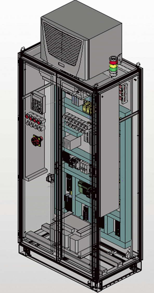
Although the traditional method of panel design is 2D, modern computer aided engineering (CAE) design software offers a 3D module. As a result, planning electrical engineering layouts is made far more efficient.
This software allows users to define a virtual 3D prototype of the mounting layout independently of the electrical schematic. Users also benefit from associative views in the mounting layout and optimal utilisation of the space available in the enclosure.
The dimensions of mounting panels, housings or enclosures can be optimally designed so that costs are reduced and consistent data for all the participating engineering disciplines ensure that the workflow towards the production is also efficient. Therefore, attrition losses through data conversion between disciplines are eliminated.
Added functions
Functions for equipping mounting panels or defining power units and valve blocks are also offered by modern day software tools. Standard compliant mounting layout and production drawings are easy to realise using associative model views, and changes in the 3D mounting layout are naturally taken into consideration in the corresponding model views and legends.
In the course of preparing mounting layouts, all the devices used in the schematic, or in the parts pre-selection, are displayed in a list or tree structure. When placing elements, the system checks whether the placement is on the correct mounting panel. Items from the schematic that have yet to be placed on the mounting panel are then indicated. The 3D mounting layout can optionally be the leading factor or it can be equipped correctly from the schematic.
Using the correct software can be a powerful designing aid for the correct implementation of the mounting layout, while also guaranteeing higher planning reliability in the product engineering process. It is also designed to operate within manufacturer specifications and enable an exact position check of devices, wire ducts and mounting rails.
Individual needs
In addition, because the design approach is individual, an entire system can be configured using settings to meet the needs of the user, company and project. This results in accelerated workflow and ultimately the desired results are achieved as quickly as possible.
The use of technology can enable components to be comfortably aligned and positioned exactly. Installation regulations and minimum spacing to manufacturer specifications are taken into account as are the correct positioning of devices, wire ducts and mounting rails, including collision checks. Also included in the entire layout is changes in the schematic or mounting layout – the system updates the associated drawings, bills of materials and legends automatically if desired. This ensures up to date, uniform and consistent data.
Devices designed in electrical engineering CAE systems can also be imported into and automatically synchronised with various programs. As a result there is no need for manual synchronisation which often produced errors. With the appropriate interface, engineers can produce and export highly precise automated drilling set-ups for leading NC machines to make enclosure cuts with greater precision than manual machine set-ups.
The right device data
Modern design software offers a number of options for accessing device data – via an integrated interface. Whether adopted directly from the component manufacturer, from any 3D CAD programs, or via various data portals, the data is imported in and, partially automatically or interactively, converted to qualified macros for the 3D mounting layout.
There are other benefits to 3D CAE design software, such as high quality 3D mounting layout, the optimum dimensioning and perfect utilisation of space, intelligent designing aids for greater planning reliability, consideration of manufacturer specifications for minimum distances, integrated mounting aids and online collision checks, accessories management for optimising placement of system components, and virtual enclosure wiring including conductor and cable length determination.
Precise, uniform, high quality documentation and production drawings produced simply and rapidly, all help accelerate every stage of design and manufacturing.
Ultimately, the realistic 3D representation offered by modern software ensures high quality data for engineering, manufacturing and operation. It facilitates the consistent creation, provision and maintenance of the documentation and accelerates the product engineering process persistently. This releases new potential productivity in engineering, increases transparency, and promotes interdisciplinary engineering processes.
EPLAN
T: 01709 704 100


